
ZipADip®Protractor Instructions
![]()
Your new ZipADip® protractor is shipped with a plastic film on both faces. It is recommended to leave the film intact to prevent scratching, especially if the ZipADip protractor will be used during field work. Remove the film if scratch protection is not needed. Please note the image resolution has been reduced for website viewing.
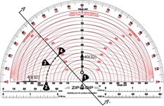
The following steps refer the to the diagram above.
To Determine Apparent Dip from Conventional Bedding Notation
- For conventional bedding notation: Position origin of ZipADip protractor at intersection of strike direction and line of cross-section.
- Find true dip value on black semicircle, interpolate as necessary (40 degrees in diagram).
- Follow black line (or interpolation) to cross-section.
- Read value from red line to determine apparent dip, interpolate as necessary. (Apparent dip is 32 degrees as shown in parenthesis.)
To Determine Apparent Dip From Dip Direction Arrows Or Oriented Cores
- Position origin of ZipADip protractor at intersection of true dip direction and line of cross-section.
- Find true dip value on black semicircle, interpolate as necessary (40 degrees in diagram).
- Follow black line (or interpolation) to cross-section.
- Read value from red line to determine apparent dip, interpolate as necessary. (Apparent dip is 32 degrees as shown in parenthesis.)
To Plot Strikes Or Bearings
- Position origin of ZipADip protractor on a north-south grid line that passes near the location where the attitude will be plotted.
- Rotate ZipADip protrctor so that the straight edge is oriented in the desired strike or bearing direction.
- Carefully slide ZipADip protractor along the north-south grid line until its straight edge passes through the attitude location.
- Draw the strike or bearing line using the straight edge of ZipADip protractor,
as a guide.
Notes:
- This method assumes that north-south construction lines have been drawn on the map at six-inch intervals.
- For strikes or bearings oriented nearly north-south, it may be necessary to use an east-west grid line and the complement of the bearing angle.